AlarvyCAD Duct Module
AlarvyCAD Duct module is an efficient 3D modelling software, specifically to create 3D CAD models and unfold of various genres of ducts. Duct module generates 3D models quickly with predefined parameters of the duct, where the values can be edited by the user.
1.0 DUCT TOOL BAR
·
When Duct
icon![]() is
clicked from the main menu, the Duct tool bar appears as shown in the Fig
1.1.
is
clicked from the main menu, the Duct tool bar appears as shown in the Fig
1.1.
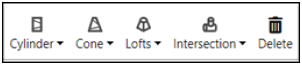
Fig 1.1 Duct tool bar
· After selecting a duct, drop-down menu appears for each duct as shown in Fig 1.2
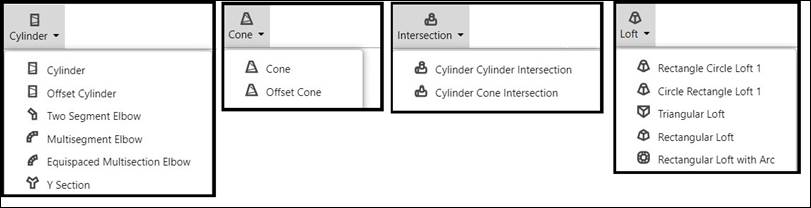
Fig 1.2 Drop-down menu
· After a particular duct is selected from the drop-down menu, parameter UI and side tool bar appears in the screen as shown in the Fig 1.3.
· The parameter UI comprises of the pictorial view of the 3D picture of a specificduct type and its respective duct parameters, options to show/hide 3D and unfold along with other duct options and options to export 3D in Step format and Unfold in DXF format.
· Side tool bar comprises of various visibility options such Zoom, Pan, Rotate and other visibility options
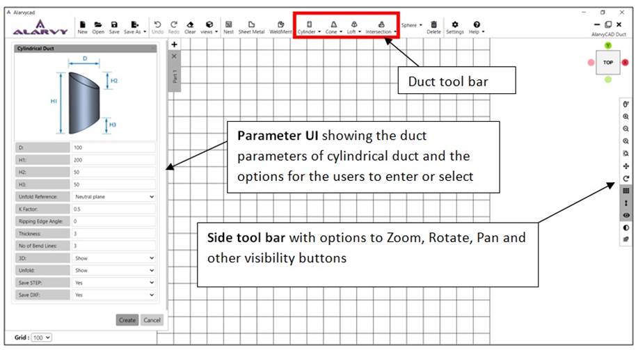
Fig 1.3 Screenshot showing the parameter UI and Side tool bar for a Cylindrical Duct
· After pressing Create option in the UI, the duct appears in the GUI as shown in the Fig 1.4 with top view orientation along with its Unfold Profile as shown in the Fig 1.4.
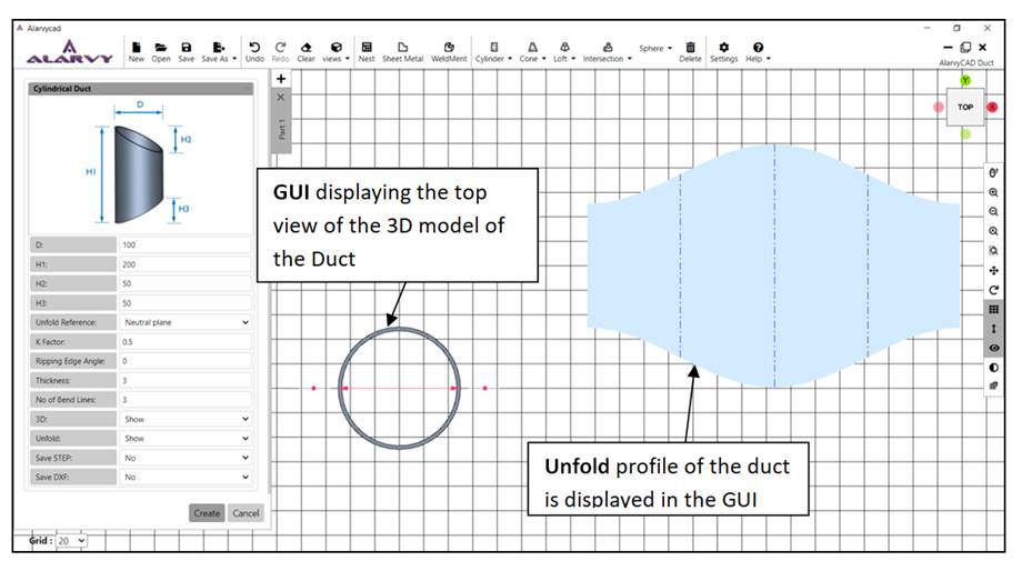
Fig 1.4 Screenshot showing the 3D model in the GUI along with the Unfold Profile
· The user can rotate the 3D model (using the left click button in the mouse) to the desired orientation, where 3D dimensioning is clearly visible as shown in the Fig 1.5.
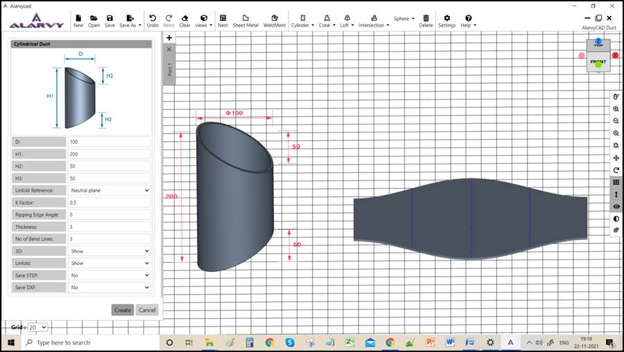
Fig 1.5 Screenshot showing the desired view of the 3D model in the GUI along with the Unfold Profile
· The user can use the scroll button to Zoom in or Zoom out for keeping the view in the desired magnification.
· The user can right click the mouse button to move or pan the 3D model in the desired location.
1.1 Parameter UI Options in the Duct Module
After the duct option is selected, parameter UI appears in left side of the main window of the program as shown in the Fig 1.1.1.
· The parameter UI shows the 3D model of the duct and the parameter of the duct, then displays options to enter the values for the parameter of the duct and the thickness of the duct.
· The visibility options of the duct such as 3D and Unfold are displayed in the parameter UI.
· Other Unfold options such as Unfold reference, K factor, Ripping Edge angle, Ripping sequence are also shown in the parameter UI, for the user to change or select alternative options
· File Export options for 3D model and Unfold profile such as “Save STEP” and “ Save DXF” are provided in the lower end if the parameter UI
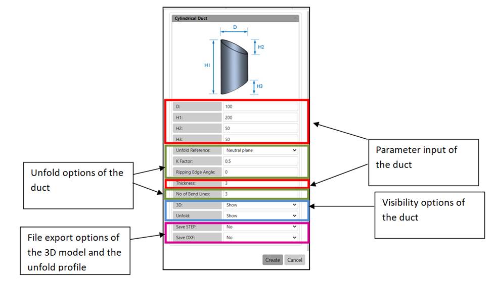
Fig 1.1.1. Parameter UI of the duct
· 3D model of the duct may be either shown or hidden in the GUI, by selecting the suitable visibility option as shown in the Fig1.1.2.
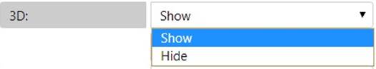
Fig 1.1.2 3D option
· Unfold of the duct may be either shown or hidden in the GUI, by selecting the suitable visibility option as shown in the Fig 1.1.3.
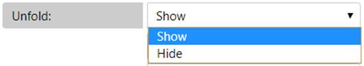
Fig 1.1.3 Unfold option
· The STEP output format of the Duct canbe savedby selecting the suitable file export option as shown in Fig 1.1.4.
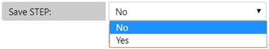
Fig 1.1.4 Save STEP option
· The DXF output format of the Duct canbe obtained by selecting the suitablefile export option as shown in Fig 1.1.5.
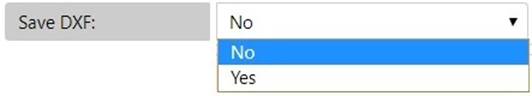
Fig 1.1.5 Save DXF option
· The Unfold reference for the duct may be changed to either neutral plane or outer surface or inner surface as shown in the Fig 1.1.6. Depending upon the selection of the unfold reference K-factor changes.
· When the Inner surface is selected in the Unfold Reference, K-Factor changes to 0, whereas when the Outer Surface is selected Unfold Reference, K-Factor changes to 1.
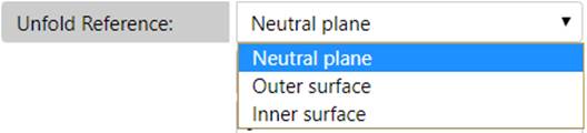
Fig 1.1.6. Unfold reference option
· The K-Factor in sheet metal working is the ratio of the neutral axis radius to the material thickness. The user may enter the value of K-Factor depending on the material in the parameter UI as shown in the Fig 1.1.7.
![]()
Fig 1.1.7. K- Factor option
· Ripping edge angle is the position of ripping edge when viewed from the top as shown in Fig 1.1.9. Ripping edge angle can bevaried from 0° (default value as shown in the Fig 1.1.8) to the desired position in the counter clockwise direction as shown in the Fig 1.1.9. The position of ripping edgefor cylindrical duct at 0° and 90° is shown in figures 1.1.10 and 1.1.11 respectively.
![]()
Fig 1.1.8 Ripping Edge angle option
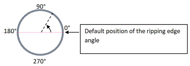
 Fig 1.1.9
Ripping Edge angle based on the top view of the cylindrical duct
Fig 1.1.9
Ripping Edge angle based on the top view of the cylindrical duct
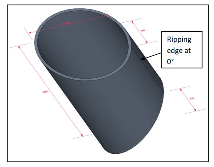
Fig 1.1.10 Ripping edge angle at 0° (Default position)
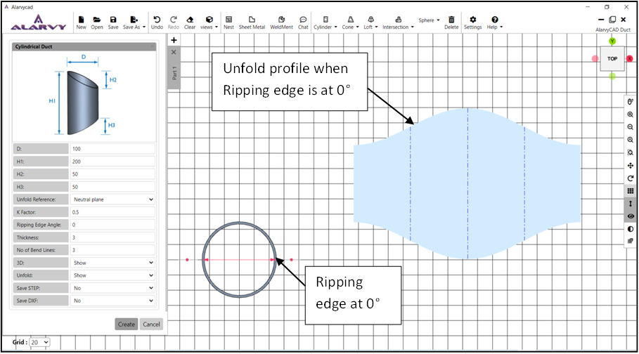
Fig 1.1.11 Top view of cylindrical duct when ripping edge angle at 0° (Default position)
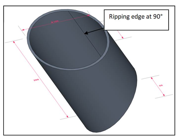
Fig 1.1.12Ripping edge angle at 90°
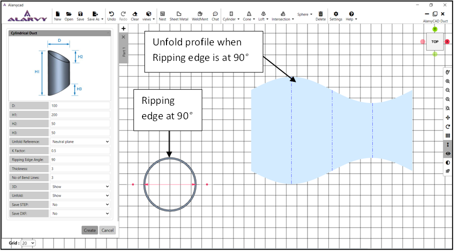
Fig 1.1.13 Top view of cylindrical duct when ripping edge angle at 90° (Default position)
- Ripping sequence is the sequence of ripping edges in the ducts like Two Segment Elbow, Multisegment Elbow, Equi-Spaced Multisegment Elbow andCylindrical Y Section, where the number of segments istwo or more. In the ripping sequence, two options are provided in the parameter UI, i.e. Alternate and Same as shown in Fig 1.1.14.
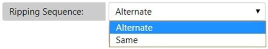
Fig 1.1.14Ripping sequence option
· If “Alternate” ripping sequence option is selected, the orientations of the ripping edges are on the alternate sides of the segments of the duct as shown in the Fig 1.1.15.
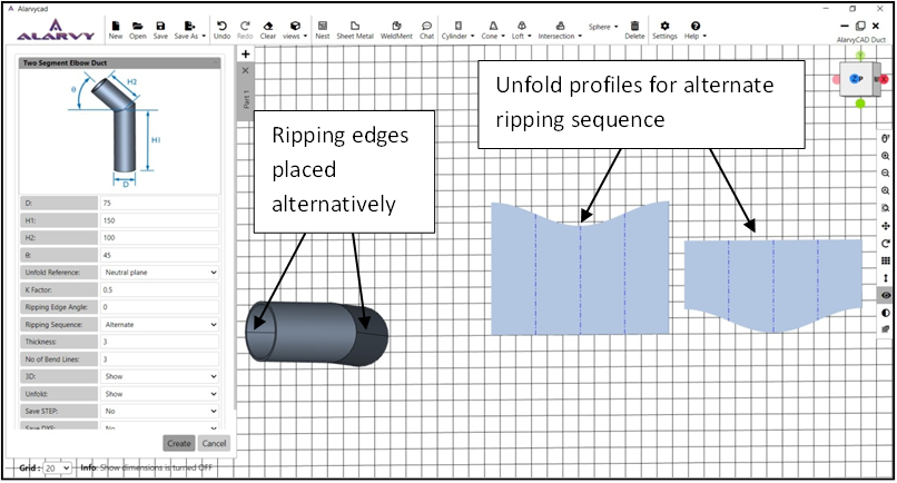
Fig 1.1.15 Alternate - Ripping sequence option of Two Segment Elbow duct
· If “Same” ripping sequence option is selected, the orientation of the ripping edges is on the same side of the segments of the duct as shown in the Fig 1.1.16.
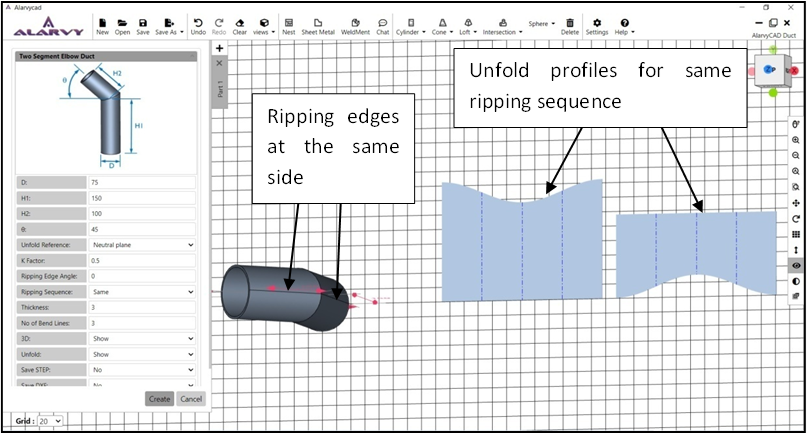
Fig 1.1.16 Same - Ripping sequence option of Two Segment Elbow duct
· Number of Bend lines option is available for the unfold profile of the ducts in the parameter UI for the unfold option as shown in the Fig 1.1.17.
![]()
Fig 1.1.17 Number of Bend lines
1.2 Cylinder
• On clicking the Cylinder duct button, the menu shows the different types of cylinders such as cylindrical duct, offset cylinder duct, Two segment Elbow duct, Multisegment Elbow duct, Equispaced Multisection Elbow duct and Y Section duct as shown in Fig 1.2.1.
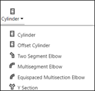
Fig 1.2.1 Cylinder duct menu
1.2.1 Cylindrical Duct
· After clicking the cylindrical duct option, the parameter UI for Cylindrical duct appears as shown in the Fig 1.2.2.
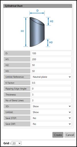
Fig 1.2.2. Parameter UI for Cylindrical Duct
· The user may enter the values for the parameters of Cylindrical Duct such as Diameter (D), Height of the cylinder (H1), Top truncated height of the cylinder (H2), Bottom truncated height of the cylinder (H3) and Thickness in the parameter UI for obtaining different dimensions of the duct.
· The parameter rules for cylindrical duct are:
1. All parameters should be > 0.
2. D should be > 2*thickness
3. H2 and H3 can be zero
· The output STEP files of the 3D model of the duct are generated using Save STEP option.
· For obtaining the DXF file of the unfold profile, Save DXF option is available.
· To show/ hide the 3D profile and the Unfold profile, 3D and Unfold options are available.
· Other Unfold options such as Unfold Reference, K-factor, Ripping Edge angle, Number of bend lines and Unfold are available for the user, changes may be done in the default value if required.
· After entering the values in the parameter UI, the user can press create button, which displays the cylindrical duct 3D model in the GUI. If the user presses cancel, the parameter UI is closed.
· In GUI, the top view of the cylindrical duct is displayed along with 3D dimensions. The user may rotate the model to the desired orientation as shown in the Fig 1.2.3., using mouse Left click and drag.
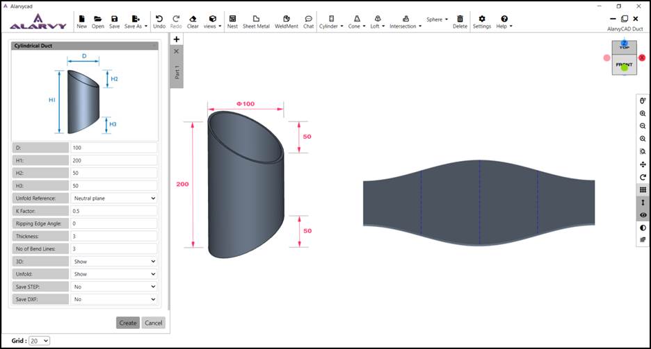
Fig 1.2.3 Cylindrical duct
1.2.2 Offset Cylinder Duct
· After clicking the Offset cylinder duct option, the parameter UI for Offset Cylindrical duct appears as shown in the Fig 1.2.4.
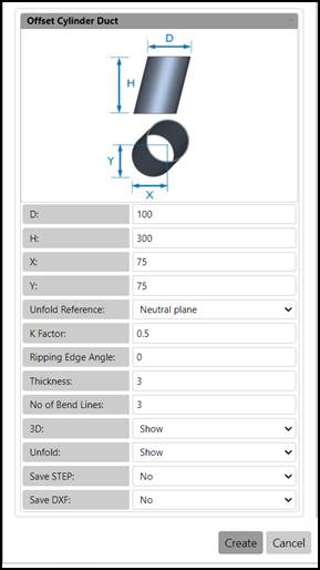
Fig 1.2.4 Parameter UI for Offset Cylinder Duct
· The user may enter the values for the parameters of Offset Cylinder Duct such as Diameter (D), Height (H), Offset distances (X,Y) and Thickness in the parameter UI for obtaining different dimensions of the duct.Offset distances are the distance of offset of top section with respect to the left extreme and bottom extreme of the base section in X and Y direction respectively.
· The parameter rules for Offset Cylinder Duct are:
1. All parameters except X and Y should be > 0.
2. X and Y values can be negative.
3. D should be > 2*thickness
· The output STEP files of the 3D model of the duct are generated using Save STEP option.
· For obtaining the DXF file of the unfold profile, Save DXF option is available.
· To show / hide the 3D model of the duct and the Unfold profile, 3D and Unfold options are available.
· Other Unfold options such as Unfold Reference, K-factor, Ripping Edge angle, Number of bend lines and Unfold are available for the user, changes may be done in the default value if required.
· After entering the values in the parameter UI, the user can press create button, which displays the offset cylinder duct 3D model in the GUI. If the user presses cancel, the parameter UI is closed.
· In GUI, the top view of the offset cylinder duct is displayed along with 3D dimensions. The user may rotate the model to the desired orientation as shown in the Fig 1.2.5., using mouse left click and drag.
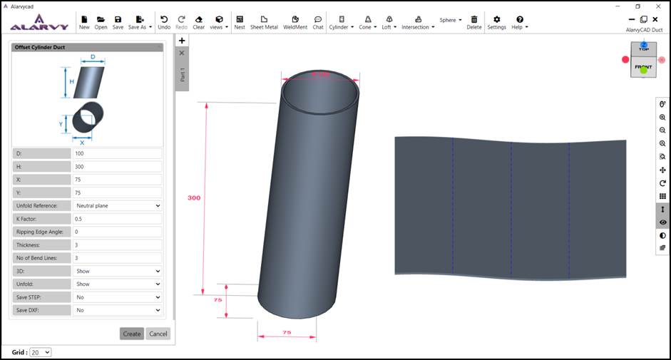
Fig 1.2.5 Offset Cylinder Duct
1.2.3 Two Segment Elbow
· After clicking the Two segment Elbow option, the parameter UI for Two segment Elbow appears as shown in the Fig 1.2.6.
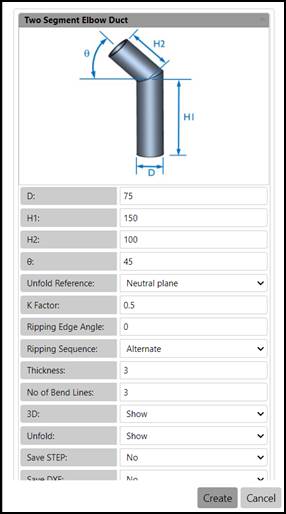
Fig 1.2.6 Parameter UI for Two segment Elbow
· The user may enter the values for the parameters of Two segment Elbow such as Diameter (D), Height of the two segments (H1, H2), Angle between the two segments (q) and Thickness in the UI for obtaining different dimensions of the duct.
· The parameter rules for Two segment Elbow are:
1. All parameters except q should be > 0.
2. q can be -89 to +269
3. D should be > 2*thickness
· The output STEP files of the 3D model of the duct are generated using Save STEP option.
· To show/ hide the 3D profile and the Unfold profile, 3D and Unfold options are available.
· Other Unfold options such as Unfold Reference, K-factor, Ripping Edge angle, Number of bend lines and Unfold are available for the user, changes may be done in the default value if required.
· After entering the values in the parameter UI, the user can press create button, which displays the Two segment Elbow duct 3D model in the GUI. If the user presses cancel, the parameter UI is closed.
· In GUI, the top view of the Two segment Elbow is displayed along with 3D dimensions. The user may rotate the model to the desired orientation as shown in the Fig 1.2.7., using mouse left click and drag.
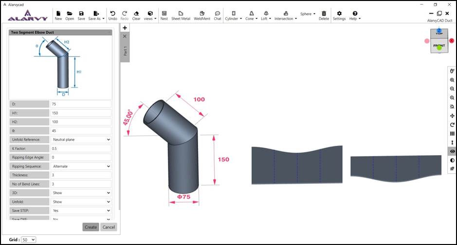
Fig 1.2.7 Two segment Elbow
1.2.4 Multisegment Elbow
· After clicking the multisegment elbow option, the parameter UI for multisegment elbow appears as shown in the Fig 1.2.8.
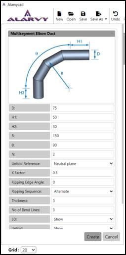
Fig 1.2.8 Parameter UI for Multisegment Elbow
· The user may enter the values for the parameters of multisegmentelbow such as Diameter (D), Extension Height of first and last segment (H1 and H2), Radius of the elbow (R), Angle of the elbow (q), Number of segments between last segment and the first segment (N) and Thickness in the parameter UI for obtaining different dimensions of the duct. If the number of segments is 2, then AlarvyCAD divides the angle into 4 segments with the first and last segment angle as q/N/2 and the intermediate segments angle as q/N.
· The parameter rules for multisegment elbow are:
1. All parameters except H1 and H2 should be > 0.
2. H1 and H2 can be >= 0.
3. D should be > 2*thickness
· The output STEP files of the 3D model of the duct are generated using Save STEP option.
· For obtaining the DXF file of the unfold profile, Save DXF option is available.
· To show/ hide the 3D profile and the Unfold profile, 3D and Unfold options are available.
· Other Unfold options such as Unfold Reference, K-factor, Ripping Edge angle, Number of bend lines and Unfold are available for the user, changes may be done in the default value if required.
· After entering the values in the parameter UI, the user can press create button, which displays the multisegmentelbow duct 3D model in the GUI. If the user presses cancel, the parameter UI is closed.
· In GUI, the top view of the multisegmentelbow is displayed along with 3D dimensions. The user may rotate the model to the desired orientation as shown in the Fig 1.2.9., using mouse left click and drag.
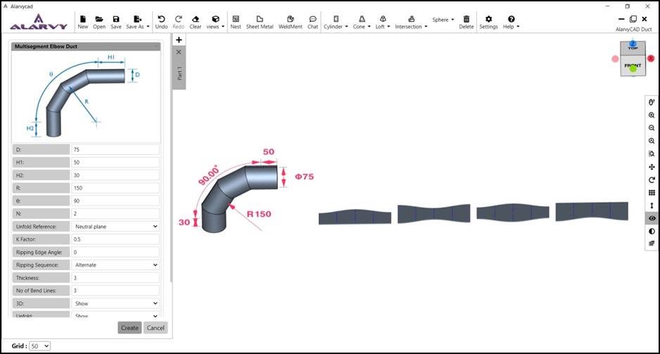
Fig 1.2.9 Multisegment Elbow
1.2.5 Equi-Spaced Multisection Elbow
· After clicking the Offset cylinder duct option, the parameter UI for equi-spaced multisection elbow appears as shown in the Fig 1.2.10.
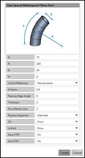
Fig 1.2.10 Parameter UI for Equi-spaced Multisection Elbow
· The user may enter the values for the parameters of equi-spacedmultisectionElbow such as Diameter (D), Radius of the elbow (R), Angle of the elbow (q), Number of segments (N) and Thickness in the parameter UI for obtaining different dimensions of the duct.If the number of segments is 4, then AlarvyCAD divides the angle into 4 segments with angle of each segment as q/N.
· The parameter rules for equi-spaced multisection Elbow are:
1. All parameters should be > 0.
2. D should be > 2*thickness
· The output STEP files of the 3D model of the duct are generated using Save STEP option.
· For obtaining the DXF file of the unfold profile, Save DXF option is available.
· To show/ hide the 3D profile and the Unfold profile, 3D and Unfold options are available.
· Other Unfold options such as Unfold Reference, K-factor, Ripping Edge angle, Number of bend lines and Unfold are available for the user, changes may be done in the default value if required.
· After entering the values in the parameter UI, the user can press create button, which displays the Equispaced Multisection Elbow duct 3D model in the GUI. If the user presses cancel, the parameter UI is closed.
· In GUI, the top view of the Equispaced Multisection Elbow is displayed along with 3D dimensions. The user may rotate the model to the desired orientation as shown in the Fig 1.2.11., using mouse left click and drag.
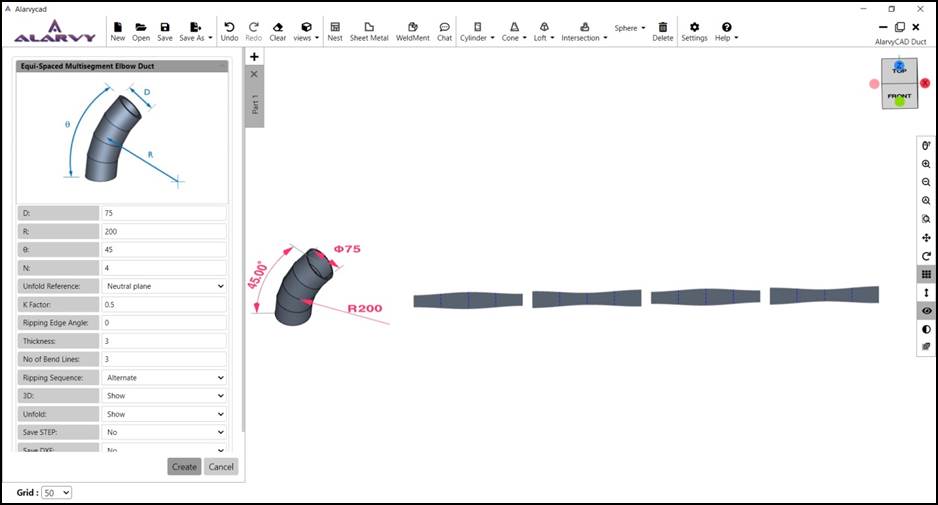
Fig 1.2.11 Equi-spacedMultisection Elbow
1.2.6 Y Section Elbow Duct
· After Clicking into the Offset cylinder duct option, the parameter UI for Y Section Elbow appears as shown in the Fig 1.2.12.

Fig 1.2.12 Parameter UI for Y Section Elbow
· The user may enter the values for the parameters of Y Section Elbow such as Diameter (D), Height (H1, H2 and H3), Angle between the inclined segments with horizontal (q1 and q2) and Thickness in the parameter UI for obtaining different dimensions of the duct.
· The parameter rules for Y Section Elbow are:
1. All parameters should be > 0.
2. q1 and q2 should not be > 90.
3. q1 should not be <= - q2.
4. q2 should not be <= - q1.
5. D should be > 2*thickness
· The output STEP files of the 3D model of the duct are generated using Save STEP option.
· For obtaining the DXF file of the unfold profile, Save DXF option is available.
· To show/ hide the 3D profile and the Unfold profile, 3D and Unfold options are available.
· Other Unfold options such as Unfold Reference, K-factor, Ripping Edge angle, Number of bend lines and Unfold are available for the user, changes may be done in the default value if required.
· After entering the values in the parameter UI, the user can press create button, which displays the Y Section Elbow duct 3D model in the GUI. If the user presses cancel, the parameter UI is closed.
· In GUI, the top view of the Y Section Elbow is displayed along with 3D dimensions. The user may rotate the model to the desired orientation as shown in the Fig 1.2.13., using mouse left click and drag.
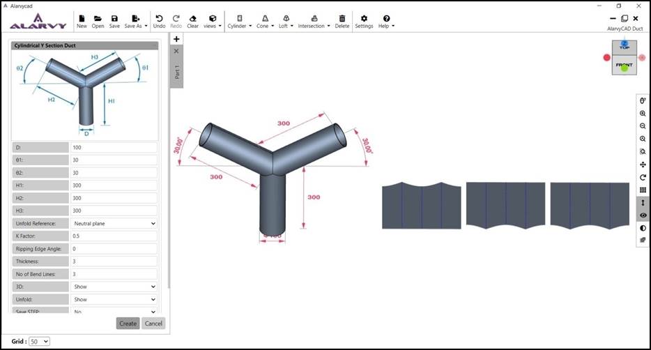
Fig 1.2.13 Y Section Elbow
1.3 Cone
• On clicking the cone duct button, the menu shows the different types of cones such as conical duct and offset cone duct as shown in Fig 1.1.1.

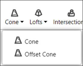
Fig 1.3.1 Cone duct menu
1.3.1 Conical Duct
· After clicking the conical duct option, the parameter UI for Conical duct appears as shown in the Fig 1.3.2.
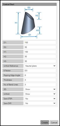
Fig 1.3.2. Parameter UI for Conical Duct
· The user may enter the values for the parameters of Conical Duct such as Bottomdiameter of the cone(D1), Top diameter of the Cone(D2),Height of the Cone (H1) , Top truncated height of the Cone (H2), Bottom truncated height of the Cone(H3) and Thickness in the parameter UI for obtaining different dimensions of the duct.
· The parameter rules for conical duct are:
- All parameters should be > 0.
- D1 and D2 should be > 2*thickness
- H2 and H3 can be Zero
· The output STEP files of the 3D model of the duct are generated using Save STEP option.
· For obtaining the DXF file of the unfold profile, Save DXF option is available.
· To show/ hide the 3D profile and the Unfold profile, 3D and Unfold options are available.
· Other Unfold options such as Unfold Reference, K-factor, Ripping Edge angle, number of bend lines and Unfold are available for the user, changes may be done in the default value if required.
· After entering the values in the parameter UI, the user can press create button, which displays the conical duct 3D model in the GUI. If the user presses cancel, the parameter UI is closed.
· In GUI, the top view of the conical duct is displayed along with 3D dimensions. The user may rotate the model to the desired orientation as shown in the Fig 1.3.3., using mouse left click and drag.
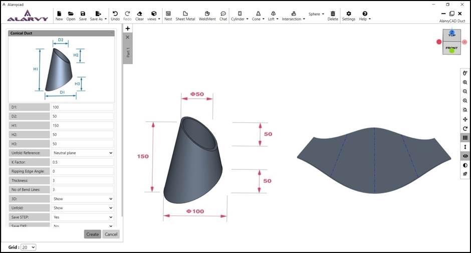
Fig 1.3.3 Conical duct
1.3.2 Offset Cone Duct
· After clicking the Offset cone duct option, the parameter UI for Offset cone duct appears as shown in the Fig 1.3.4.
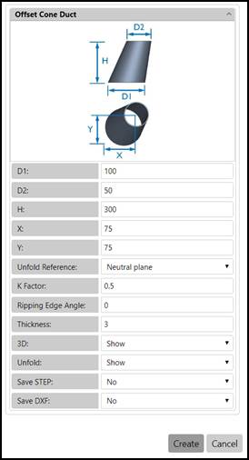
Fig 1.3.4 Parameter UI for Offset Cone Duct
· The user may enter the values for the parameters of Offset Cone Duct such as Bottom diameter of the cone (D1), Top Diameterof the cone (D2), Height (H), Offset distances (X,Y) and Thickness in the parameter UI for obtaining different dimensions of the duct.Offset distances are the distance of offset of top section with respect to the left extreme and bottom extreme of the base section in X and Y direction respectively.
· The parameter rules for Offset Cone Duct are:
1. All parameters except X and Y should be > 0.
2. X and Y values can be negative.
3. D1 and D2 should be > 2*thickness
· The output STEP files of the 3D model of the duct are generated using Save STEP option.
· For obtaining the DXF file of the unfold profile, Save DXF option is available.
· To show / hide the 3D model of the duct and the Unfold profile, 3D and Unfold options are available.
· Other Unfold options such as Unfold Reference, K-factor, Ripping Edge angle, number of bend lines and Unfold are available for the user, changes may be done in the default value if required.
· After entering the values in the parameter UI, the user can press create button, which displays the offset cone duct 3D model in the GUI. If the user presses cancel, the parameter UI is closed.
· In GUI, the top view of the offset cone duct is displayed along with 3D dimensions. The user may rotate the model to the desired orientation as shown in the Fig 1.2.5., using mouse left click and drag.
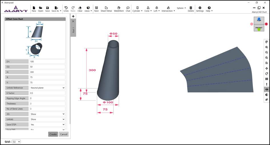
Fig 1.3.5 Offset Cone Duct
1.4 Loft
• On clicking the Loft duct button, the loft menu shows different types of loftssuch as Rectangle Circle Loft, Circle Rectangle Loft, Triangular Loft, Rectangular Loft and Rectangular Loft with arc as shown in Fig 1.4.1.
![]()
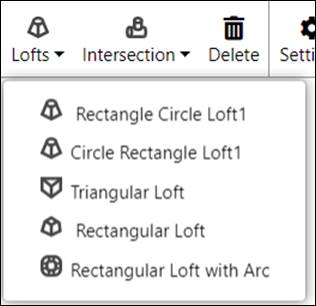
Fig 1.4 Loft duct menu
1.4.1 Rectangle Circle loft
· After clicking the Rectangle Circle Loft option, the parameter UI for Rectangle Circle Loft appears as shown in the Fig 1.4.1.
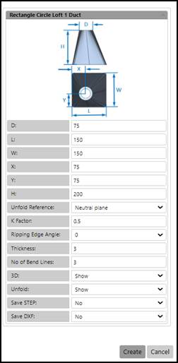
Fig 1.4.1. Parameter UI for Rectangle Circle Loft
· The user may enter the values for the parameters of Rectangle Circle Loft such as Diameter of the circle (D), Length of the rectangle(L), Width of the rectangle (W),Offset distance of the circle from the left and bottom edges of the rectangle (X,Y),Height of the loft (H) and Thickness in the parameter UI for obtaining different dimensions of the duct.
· The parameter rules for Rectangle Circle Loft are:
1. All parameters except X and Y should be > 0.
2. X and Y values can be negative.
3. D, W, L should be > 2*thickness
· The output STEP files of the 3D model of the duct are generated using Save STEP option.
· For obtaining the DXF file of the unfold profile, Save DXF option is available.
· To show/ hide the 3D profile and the Unfold profile, 3D and Unfold options are available.
· Other Unfold options such as Unfold Reference, K-factor, Ripping Edge angle, number of bend lines and Unfold are available for the user, changes may be done in the default value if required.
· After entering the values in the parameter UI, the user can press create button, which displays the Rectangle Circle Loft 3D model in the GUI. If the user presses cancel, the parameter UI is closed.
· In GUI, the top view of the Rectangle Circle Loft is displayed along with 3D dimensions. The user may rotate the model to the desired orientation as shown in the Fig 1.4.2., using mouse left click and drag.
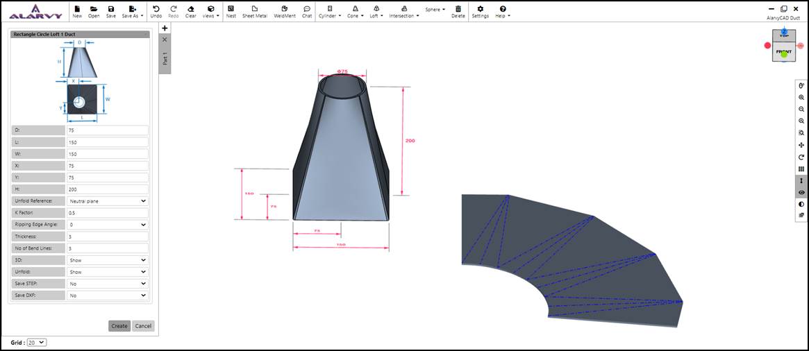
Fig 1.4.2 Rectangle Circle Loft
1.4.2 Circle Rectangle loft
· After clicking the Circle Rectangle loft duct option, the parameter UI for Circle Rectangle loft duct appears as shown in the Fig 1.4.3.
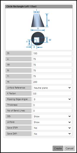
Fig 1.4.3Parameter UI for Circle Rectangle loft Duct
· The user may enter the values for the parameters of Circle Rectangle loft Duct such as Diameter of the circle (D), Length of the rectangle(L), Width of the rectangle (W),Offset distance of the rectangle centre from the horizontal and vertical tangents of the circle (X,Y),Height of the loft (H) and Thickness in the parameter UI for obtaining different dimensions of the duct.
· The parameter rules for Circle Rectangle loft Duct are:
1. All parameters except X and Y should be > 0.
2. X and Y values can be negative.
3. D1 and D2 should be > 2*thickness
· The output STEP files of the 3D model of the duct are generated using Save STEP option.
· For obtaining the DXF file of the unfold profile, Save DXF option is available.
· To show / hide the 3D model of the duct and the Unfold profile, 3D and Unfold options are available.
· Other Unfold options such as Unfold Reference, K-factor, Ripping Edge angle, number of bend lines and Unfold are available for the user, changes may be done in the default value if required.
· After entering the values in the parameter UI, the user can press create button, which displays the Circle Rectangle loft duct 3D model in the GUI. If the user presses cancel, the parameter UI is closed.
· In GUI, the top view of the Circle Rectangle loft duct is displayed along with 3D dimensions. The user may rotate the model to the desired orientation as shown in the Fig 1.4.4., using mouse left click and drag.
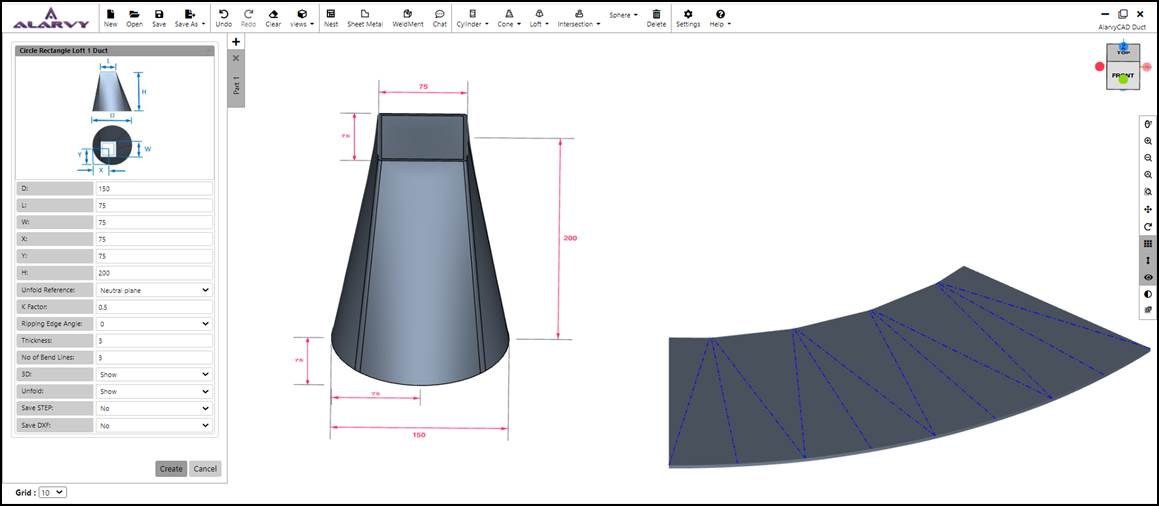
Fig 1.4.4 Circle Rectangle loft Duct
1.4.3 Triangular loft
· After clicking the Triangular loft duct option, the parameter UI for Triangular loft duct appears as shown in the Fig 1.4.5.
· The user may enter the values for the parameters of Triangular loft Duct such as Length of the edges of the triangular loft (W1, W2, W3), Height at the vertices of the triangular loft (H1, H2, H3) and Thickness in the parameter UI for obtaining different dimensions of the duct.
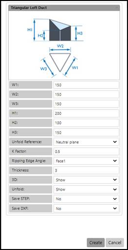
Fig 1.4.5Parameter UI for Triangular loft Duct
· The parameter rules for Triangular loft duct are:
1. All parameters should be > 0.
2. The sides of a triangle rule asserts that the sum of the lengths of any two sides of a triangle has to be greater than the length of the third side. i.e. W1+W2 should be > W3; and W1+W3 should be > W2; and W2+W3 should be > W1.
· The output STEP files of the 3D model of the duct are generated using Save STEP option.
· For obtaining the DXF file of the unfold profile, Save DXF option is available.
· To show/ hide the 3D profile and the Unfold profile, 3D and Unfold options are available.
· Other Unfold options such as Unfold Reference, K-factor, Ripping Edge angle, number of bend lines and Unfold are available for the user, changes may be done in the default value if required.
· Here the ripping edge angle option is based on the three faces of triangular loft, which is mentioned in the drop-down menu as shown in the Fig 1.4.6. The ripping edge is placed in the centre of the selected face.
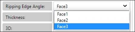
Fig 1.4.6 Ripping edge angle option – Triangular Loft
· After entering the values in the parameter UI, the user can press create button, which displays the Triangular loft duct 3D model in the GUI. If the user presses cancel, the parameter UI is closed.
· In GUI, the top view of the Triangular loft duct is displayed along with 3D dimensions. The user may rotate the model to the desired orientation as shown in the Fig 1.4.7., using mouse left click and drag.
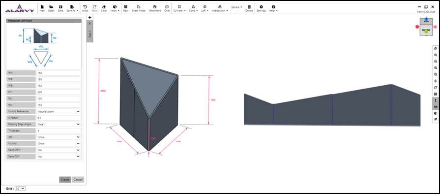
Fig 1.4.7 Triangular loft duct
1.4.4 Rectangular loft
· After clicking the Rectangular loft duct option, the parameter UI for Rectangular loft duct appears as shown in the Fig 1.4.8.
· The user may enter the values for the parameters of Rectangular loft Duct such as Lengths of the bottom and top rectangle(L1, L2), Widths of the bottom and top rectangle (W1, W2), Offset of the top rectangle from the left and bottom edges of the bottom rectangle (X,Y) ,Height of the rectangular loft (H) and Thickness in the parameter UI for obtaining different dimensions of the duct.
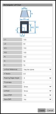
Fig 1.4.8 Parameter UI for Rectangular loft Duct
· The parameter rules for Rectangular loft duct are:
1. All parameters except X and Y should be > 0.
2. X and Y values can be negative.
3. L1, L2, W1, W,2 should be > 2*thickness
· The output STEP files of the 3D model of the duct are generated using Save STEP option.
· For obtaining the DXF file of the unfold profile, Save DXF option is available.
· To show/ hide the 3D profile and the Unfold profile, 3D and Unfold options are available.
· Other Unfold options such as Unfold Reference, K-factor, Ripping Edge angle, number of bend lines and Unfold are available for the user, changes may be done in the default value if required.
· Ripping edge angle can be selected by the user from the drop-down menu as shown in the Fig 1.4.9.
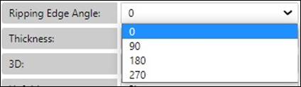
Fig 1.4.9 Ripping edge angle option – Rectangular Loft
· After entering the values in the parameter UI, the user can press create button, which displays the Rectangular loft duct 3D model in the GUI. If the user presses cancel, the parameter UI is closed.
· In GUI, the top view of the Rectangular loft duct is displayed along with 3D dimensions. The user may rotate the model to the desired orientation using Left click of the mouse as shown in the Fig 1.4.10.
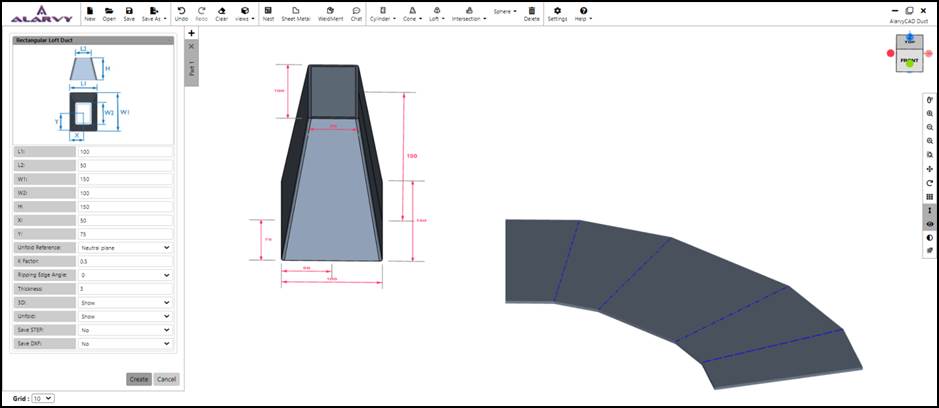
Fig 1.4.10 Rectangular loft duct
1.4.5 Rectangular loft with arc
· After clicking the Rectangular loft with arc duct option, the parameter UI for Rectangular loft with arc duct appears as shown in the Fig 1.4.11.
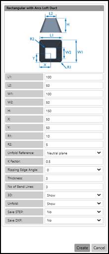
Fig 1.4.11 Parameter UI for Rectangular loft with arc Duct
· The user may enter the values for the parameters of Rectangular loftwith arc Duct such as Length of the bottom and top rectangle(L1, L2), Width of the bottom and top rectangle (W1, W2), Offset of the top rectangle from the left and bottom edges of the bottom rectangle (X,Y), Fillet radius of the bottom and top rectangle (R1,R2),Height of the rectangular loft (H) and Thickness in the parameter UI for obtaining different dimensions of the duct.
· The parameter rules for Rectangular loft with arc duct are:
1. R1 should be <Min(L1, W1)/2.
2. R2 should be <Min(L2, W2)/2.
3. All parameters except X and Y should be > 0.
4. X and Y values can be negative.
5. L1, L2, W1, W,2 should be > 2*thickness
· The output STEP files of the 3D model of the duct are generated using Save STEP option.
· For obtaining the DXF file of the unfold profile, Save DXF option is available.
· To show/ hide the 3D profile and the Unfold profile, 3D and Unfold options are available.
· Other Unfold options such as Unfold Reference, K-factor, Ripping Edge angle, number of bend lines and Unfold are available for the user, changes may be done in the default value if required.
· Ripping edge angle can be selected by the user from the drop-down menu as shown in the Fig 1.4.9.
· After entering the values in the parameter UI, the user can press create button, which displays the Rectangular loft with arc duct 3D model in the GUI. If the user presses cancel, the parameter UI is closed.
· In GUI, the top view of the Rectangular loft with arc duct is displayed along with 3D dimensions. The user may rotate the model to the desired orientation as shown in the Fig 1.4.12., using mouse left click and drag.
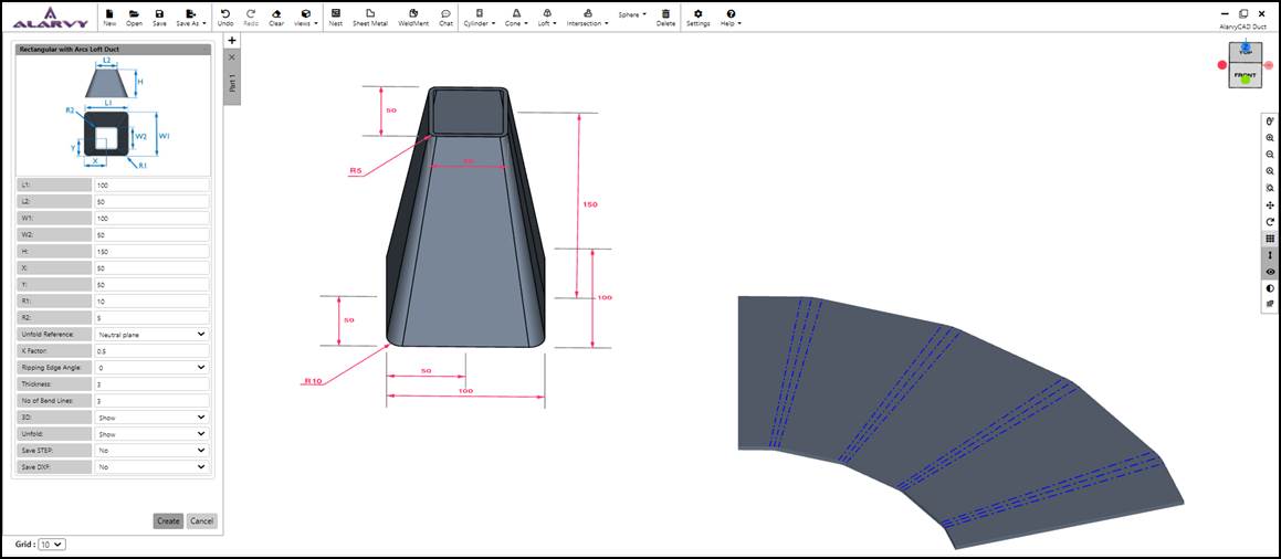
Fig 1.4.12 Rectangular loft with arc duct
1.5 Intersection
• On clicking the Intersection duct button, the menu shows the different types of Intersections such as Cylinder Cylinder Intersection duct and Cylinder Cone Intersection duct as shown in Fig 1.5.
![]()
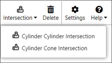
Fig 1.5 Intersection duct menu
1.5.1 Cylinder CylinderIntersection Duct
· After clicking the Cylinder Cylinder Intersection duct option, the parameter UI for Cylinder Cylinder Intersection duct appears as shown in the Fig 1.5.1.
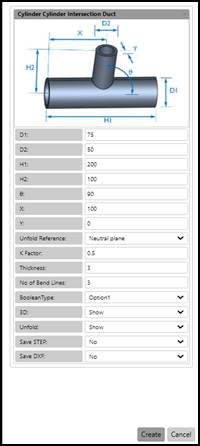
Fig 1.5.1. Parameter UI for Cylinder Cylinder Intersection Duct
· The user may enter the values for the parameters of Cylinder Cylinder Intersection Duct such as Diameter of Cylinder1 (D1), Diameter of Cylinder2 (D2),Length of Cylinder1 (H1), Height of the Cylinder2 with reference to the center of Cylinder1 (H2), Angle between Cylinder1 and Cylinder2 (Ɵ), Offset distance of Cylinder2 with reference to theleft edge of Cylinder1 (X) and the offset distance of center of Cylinder2(Y) with respect to axis of Cylinder1 and Thickness in the parameter UI for obtaining different dimensions of the duct.
· The parameter rules for Cylinder Cylinder Intersection duct are:
1. If ((Booleantype == Option1)(Booleantype == || Option2)) then D2 should be <= D1 -2t elseif (Booleantype == Option3) then D2 should be <= D1.
2. H2 should be > D1/2.
3. X should be > D2/2.
4. H1 should be > X+(D2/2).
5. Y should be <±((D1-D2)/2).
6. D1 and D2 should be > 2*thickness
7. All parameters should be > 0.
· The output STEP files of the 3D model of the duct are generated using Save STEP option.
· For obtaining the DXF file of the unfold profile, Save DXF option is available.
· To show/ hide the 3D profile and the Unfold profile, 3D and Unfold options are available.
· Other Unfold options such as Unfold Reference, K-factor, Ripping Edge angle, number of Bend lines and Unfold are available for the user, changes may be done in the default value if required.
· After entering the values in the parameter UI, the user can press create button, which displays the Cylinder Cylinder Intersection duct 3D model in the GUI. If the user presses cancel, the parameter UI is closed.
· In GUI, the top view of the Cylinder Cylinder Intersection duct is displayed along with 3D dimensions. The user may rotate the model to the desired orientation as shown in the Fig 1.5.2., using mouse left click and drag.
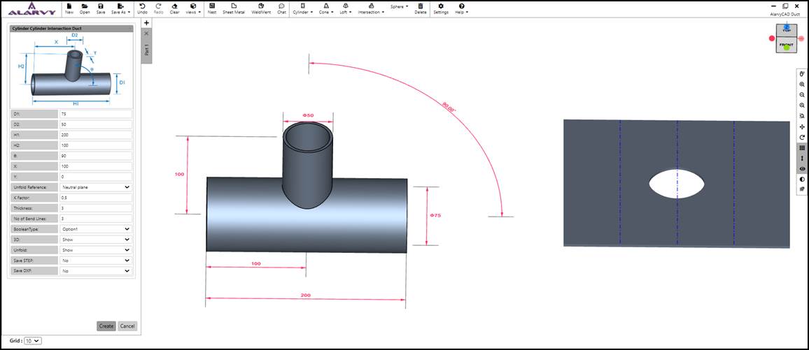
Fig 1.5.2 Cylinder Cylinder Intersection duct
· There are three different Boolean types available in parameter UI. The Fig 1.5.3 given below represents the orientation of Cylinder 2 with respect to Cylinder 1 for Option1,Option2 andOption3.


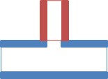
(a) Option1 (b)Option2 (c)Option3
Fig 1.5.3 Boolean options of Cylinder Cylinder Intersection
1.5.2 Cylinder Cone Intersection Duct
· After clicking the Cylinder Cone Intersection duct option, the parameter UI for Cylinder Cone Intersection duct appears as shown in the Fig 1.5.4.
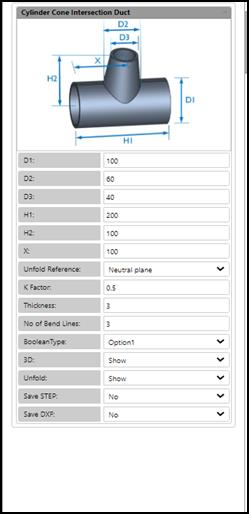
Fig 1.5.4Parameter UI for Cylinder Cone Intersection Duct
· The user may enter the values for the parameters of Cylinder Cone Intersection Duct such as Diameter of the cylinder (D1), Top diameter of the Cone (D2), Bottom diameter of the cone (D3), Length of the cylinder (H1), Height of the cone with respect to the center of the cylinder (H2), Offset distance of the cone from the left edge of the cylinder (X) and Thickness in the parameter UI for obtaining different dimensions of the duct.
· The parameter rules for Cylinder Cone Intersection Duct are:
1. D3<D2.
2. H2 > D1/2.
3. X value cannot be lesser than D2/2.
4. H1 should be greater than X+(D2/2).
5. If ((Booleantype == Option1)(Booleantype == || Option2)) then D1’ = D1 -2t
elseif (Booleantype == Option3) then D1’ = D1.
theta = ATAN(H2/((D1’-D3)/2));
MaxD2 = 2*(((H2-(D1/2))/TAN(theta))+D3
D2 should be <= MaxD2
6. D1 and D2 should be > 2*thickness
7. All parameters should be > 0.
· The output STEP files of the 3D model of the duct are generated using Save STEP option.
· For obtaining the DXF file of the unfold profile, Save DXF option is available.
· To show / hide the 3D model of the duct and the Unfold profile, 3D and Unfold options are available.
· Other Unfold options such as Unfold Reference, K-factor, Ripping Edge angle, number of Bend lines and Unfold are available for the user, changes may be done in the default value if required.
· After entering the values in the parameter UI, the user can press create button, which displays the Cylinder Cone Intersection duct 3D model in the GUI. If the user presses cancel, the parameter UI is closed.
· In GUI, the top view of the Cylinder Cone Intersection duct is displayed along with 3D dimensions. The user may rotate the model to the desired orientation as shown in the Fig 1.5.5., using mouse left click and drag.
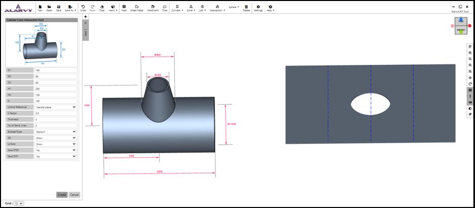
Fig 1.5.5 Cylinder Cone Intersection Duct
· There are three different Boolean options available in parameter UI. The Fig 1.5.6 given below represents the orientation of Cylinder 2with respect to Cylinder 1 for Option1, Option2 and Option3.


(a) Option1 (b) Option2 (c) Option3
Fig 1.5.6 Boolean options of Cylinder Cone Intersection
2.0 Side Toolbar Features
2.1 Open Mouse Help panel
• Click on![]() Open Mouse
Help panel to view the mouse buttons help menu.
Open Mouse
Help panel to view the mouse buttons help menu.
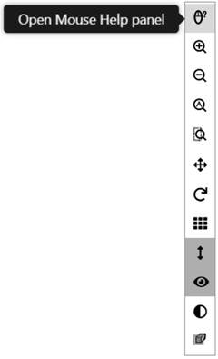
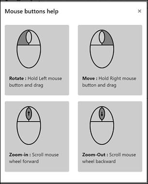
Fig 2.1.1 Mouse help panel
2.2 Zoom In
• On Click ![]() ,
it provides zoom in functionality.
,
it provides zoom in functionality.
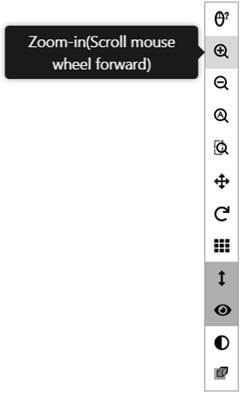
Fig 2.2.1 Zoom in button
2.3 Zoom Out
• Click on ![]() ,
provides Zoom out functionality.
,
provides Zoom out functionality.
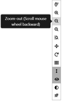
Fig 2.3.1 Zoom Out button
2.4 Zoom All
• Click on ![]() fits the model to the window.
fits the model to the window.
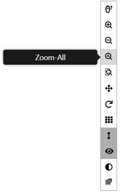
Fig 2.4.1 Zoom All button
2.5 Zoom Window
• Click on ![]() provides a
window to zoom in required features in the model.
provides a
window to zoom in required features in the model.
• After clicking Zoom Window, click on screen and drag. This draws a window area which will be zoomed on mouse release.
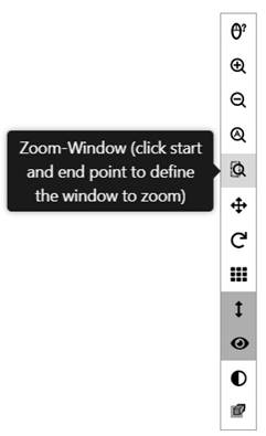
Fig 2.5.1 Zoom Window button
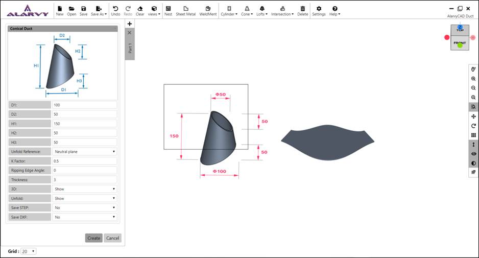
Fig 2.5.2 Model with zoom window
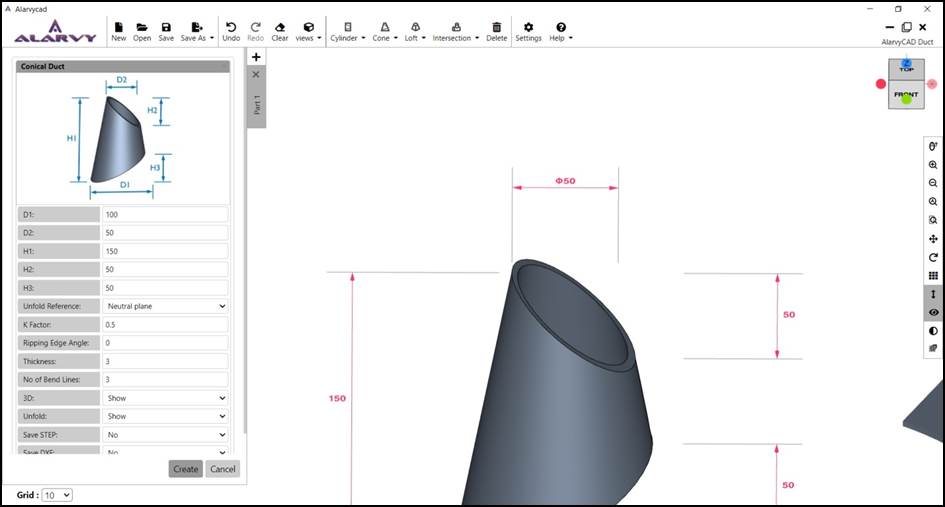
Fig 2.5.3 Zoomed view of the model
2.6 Move (Pan)
• Hold Right mouse button and drag to move the model.
• Click on ![]() pan
option is activated with left click
pan
option is activated with left click
• On mouse release, Pan is reset. So model is rotated on left click and drag
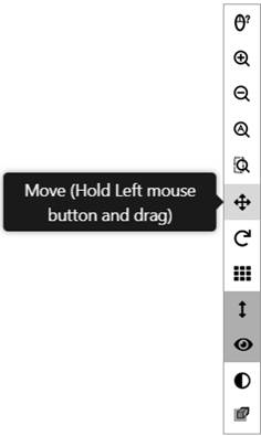
Fig 2.6.1 Pan button
2.7 Rotate
• On click ![]() hold
left mouse button and drag to rotate the model.
hold
left mouse button and drag to rotate the model.
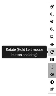
Fig 2.7.1 Rotate button
2.8 Grid ON/OFF
• On click ![]() Switches
the Grid to ON or OFF.
Switches
the Grid to ON or OFF.
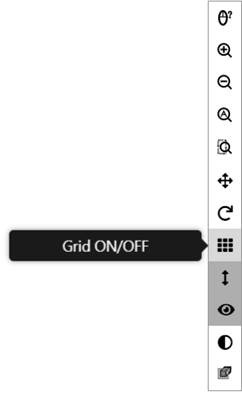
Fig 2.8.1 Grid turned ON
2.9 Dimensions ON/OFF
• On click ![]() model
dimensions can be turned ON/OFF using this button.
model
dimensions can be turned ON/OFF using this button.
• By default, Dimensions is ON
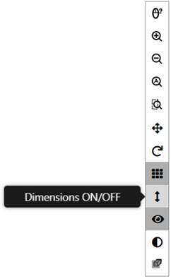
Fig 2.9.1 Dimensions ON/OFF button
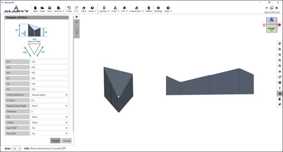
Fig 2.9.2 Model with dimensions turned OFF
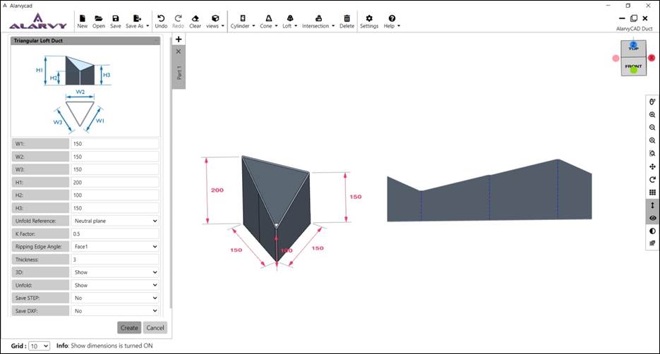
Fig 2.9.3 Model with dimensions turned ON
2.10 3D Preview ON/OFF
• On clicking ![]() switches 3D
Preview OFF, hides the model and 2D sketch is shown.
switches 3D
Preview OFF, hides the model and 2D sketch is shown.
• On clicking![]() switches 3D Preview ON, shows the solid 3D Model.
switches 3D Preview ON, shows the solid 3D Model.
• By default, 3D Preview is ON.
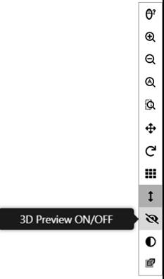
Fig 2.10.1 3D preview ON/OFF button
2.11 Transparency ON/OFF
• On clicking ![]() Transparency
button ON, shows the transparent model which clearly depicts the inner and
outer details of the model.
Transparency
button ON, shows the transparent model which clearly depicts the inner and
outer details of the model.
• By default, Transparency is OFF.

Fig 2.11.1 Transparency ON/OFF button
3.0 Plane Section Toolbar
• Click on the plane section button in side toolbar to open Plane Section Toolbar.
• This toolbar has XY plane, YZ plane, ZX plane, Face plane and Invert plane.
• Create a 3D Model. Then click one of these buttons to view the respective cross sections of the model in their corresponding plane.
![]()
Fig 3.1 Plane section toolbar
3.1 XY – Plane
• Create a 3D Model.
• Click on XY–Plane button as shown in Fig 3.1.1.
• A transparent sectional plane appears on the model in XY plane.
• Click on the plane and move it to view the cross section of the model in XY direction.
• To exit the planar view, press Esc or ‘X’ button in section toolbar.
• Refer Fig 3.1.2.
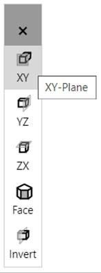
Fig 3.1.1 XY plane button
Fig 3.1.2 XY plane in model
3.2 YZ - Plane
• Create a 3D Model.
• Click on YZ–Plane button as shown in Fig 3.2.1.
• A transparent sectional plane appears on the model in YZ plane.
• Click on the plane and move it to view the cross section of the model in YZ direction.
• To exit the planar view, press Esc or ‘ X ’ button in section toolbar.
• Refer Figure3.2.2.
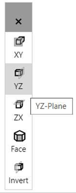
Fig 3.2.1YZ plane button
Fig 3.2.2 YZ plane in model
3.3 ZX – Plane
• Create a 3D Model.
• Click on ZX–Plane button as shown in Fig 3.3.1.
• A transparent sectional plane appears on the model in ZX plane.
• Click on the plane and move it to view the cross section of the model in ZX direction.
• To exit the planar view, press Esc or ‘ X ’ button in section toolbar.
• Refer Figure3.3.2.
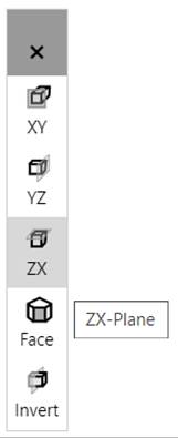
Fig 3.3.1ZX plane button
Fig 3.3.2 ZX plane in model
3.4 Face – Plane
• Create a 3D Model.
• Click on Face button in side toolbar thenClick on a face of the model to choose the plane direction.
• A transparent sectional plane appears on the model in selected plane.
• Click on the plane and move it to view the cross section of the model.
• To exit the planar view, press Esc or ‘ X ’ button in section toolbar.
• Refer Fig 3.4.2.
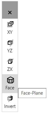
Fig 3.4.1 Face plane button
Fig 3.4.2 Face plane on model
3.5 Invert – Plane
• Create a 3D Model.
• Click on Face button in side toolbar then Click on a face of the model to choose the plane direction. Ref Fig 3.5.1.
• A transparent sectional plane appears on the model in selected plane.
• Now Click on Invert button in side tool bar. This inverts the planar view. Ref Fig 3.5.2.
• Click on the plane and move it to view the cross section of the model.
• To exit the planar view, press Esc or ‘ X ’ button in section toolbar.
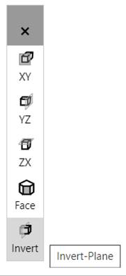
Fig 3.5.1Invert-Plane button
Fig 3.5.2 Invert-Plane on model
4.0 Page Side Toolbar
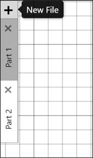
Fig 4.1 Page side toolbar
• Multiple Pages/Tab feature is supported in this application.
• To add a new page, Click ‘ + ’ button or Ctrl + N key.
• To Switch between pages, click on the respective tab.
• Each page can have a separate view like Top, Bottom, Left, Right, Front, Back, Default view.
• Each Page has its own Grid, Models, Rotator position, etc.
• Also, every page can be rotated, moved independent of each other.
• To close a tab/page Click on ‘ X ’ button in the respective page in side tab.
5.0 File Module Toolbar
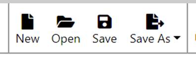
Fig 5.1 File module toolbar

Fig 5.1.1 New button
5.1 New
• On clicking New, Adds a new page to the application.
• New page can also be added by Clicking on ‘ + ’ button in Page Side toolbar or pressing Ctrl + N key.
• Refer Section 4 for new page addition.
5.2 Open
• On clicking File, Open dialog box appears then Browse for *.alarvy format file.
• Revolve Model along with all the sub features are created from the inputs given in *.alarvy file and shown in the current page.
• Refer section 9 for Alarvy file format (*.alarvy).
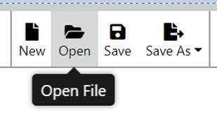
Fig 5.2.1 Open
5.3 Save
• On clicking Save, File Save dialog box appears then Choose a folder path to save the file.
• Saves the model data in the current page in *.alarvy format.
• Refer section 9 for Alarvy file format (*.alarvy).
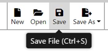
Fig 5.3.1 Save file
5.4 Save As
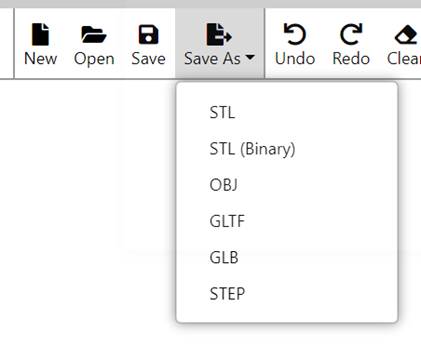
Fig 5.4.1 Save As
5.4.1 Save As STL
• On clicking Save As, STL File then Save dialog box appears, after that Choose a folder path to save the file as STL.
• Saves the model in current page in ASCII STL format.
• In case of storing either 3D or Unfold profiles or both in the single file, using below Model dialog is shown. Ref Fig 5.4.2, Check or Uncheck the checkbox next to the models to save them in STL file.
• By Default, both 3D and Unfold options are selected.
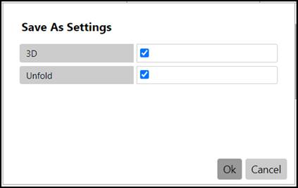
Fig 5.4.2 Save As 3D or unfold profile setting
5.4.2 Save As STL (Binary)
• On clicking Save As STL , File Save dialog box appears then Choose a folder path to save the file as STL.
• Saves the model in current page in Binary STL format.
• In case of storing either 3D or Unfold profiles or both in the single file, using below Model dialog is shown. Ref Fig 5.4.2, Check or Uncheck the checkbox next to the models to save them in STL file.
• By Default, both 3D and Unfold options are selected.
5.4.3 Save As OBJ
• On clicking Save As OBJ, File Save dialog box appears then Choose a folder path to save the file as OBJ.
• Saves the model in current page in *.OBJ format.
• In case of storing either 3D or Unfold profiles or both in the single file, using below Model dialog is shown. Ref Fig 5.4.2, Check or Uncheck the checkbox next to the models to save them in OBJ file.
• By Default, both 3D and Unfold options are selected.
5.4.4 Save As GLTF
• On clicking Save As GLTF, File Save dialog box appears then Choose a folder path to save the file as GLTF.
• Saves the model in current page in *.GLTF format.
• Incase of storing either 3D or Unfold profiles or both in the single file, using below Model dialog is shown. Ref Fig 5.4.2, Check or Uncheck the checkbox next to the models to save them in GLTF file.
• By Default, both 3D and Unfold options are selected.
5.4.5 Save As GLB
• On clicking Save As GLB, File Save dialog box appears then Choose a folder path to save the file as GLB.
• Saves the model in current page in *.GLB format.
• Incase of storing either 3D or Unfold profiles or both in the single file, using below Model dialog is shown. Ref Fig 5.4.2, Check or Uncheck the checkbox next to the models to save them in GLB file.
• By Default, both 3D and Unfold options are selected.
5.4.6 Save As STEP
• On clicking Save As STEP , File Save dialog box appears then Choose a folder path to save the file as STEP.
• Saves the model in current page in *.STEP format.
• Incase of storing 3D model, using below Model dialog is shown. Ref Fig 5.4.2, the checkbox next to the 3D model is only activated to save them in STEP file.
5.4.7 Save As DXF
• On clicking Save As DXF, File Save dialog box appears then Choose a folder path to save the file as DXF.
• Saves the model in current page in *.STEP format.
• Incase of storing the unfold DXF file, using below Model dialog is shown. Ref Fig 5.4.2, the checkbox next to the Unfold profile is only activated to save them in DXF file.
6.0 View Module Toolbar
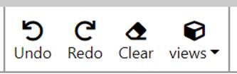
Fig 6.1 View toolbar
6.1 Undo
• On clicking Undo, Undoes an operation in the active page only.
• While creating a duct, clicking on Undo will remove the duct
• Keyboard shortcut – Ctrl + Z.
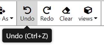
Fig 6.1.1 Undo
6.2 Redo
• On clicking Redo, Redoes an operation in the active page only.
• After the clicking Undo, Redo option will get activated and it will bring back the duct in the active page.
• Keyboard shortcut – Ctrl + Y.
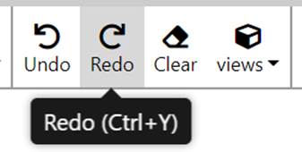
Fig 6.2.1 Redo
6.3 Clear
• On clicking Clear, Removes duct model in the active page.
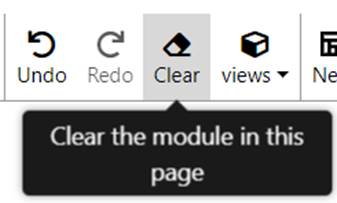
Fig 6.3.1 Clear
6.4 Views
• Selects the predefined 3D View of the model.
• On clicking Views, then default View.
• This displays the active page/model in Isometric view.
• Refer Figure6.4.2.
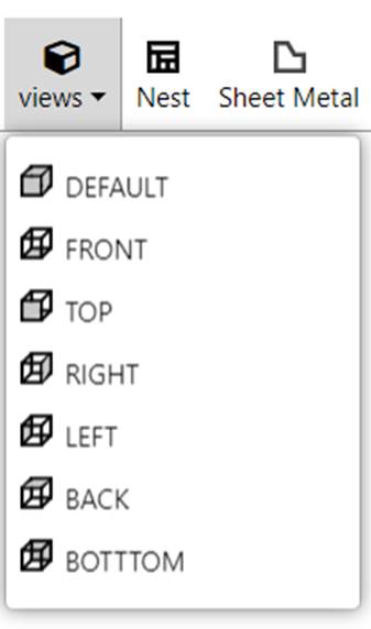
Fig 6.4.1 Views
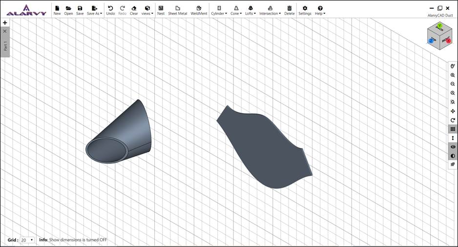
Fig 6.4.2 Default view
• On clicking Views, then Top View.
• This displays the active page in Top view i.e., XY Plane and +Z direction.
• Refer Fig 6.4.3.
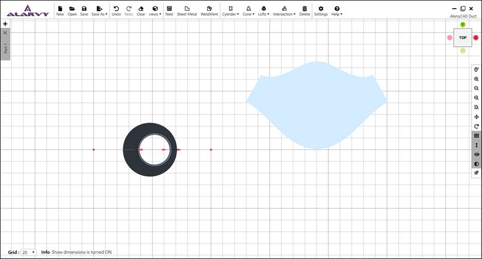
Fig 6.4.3 Top view
• On clicking Views then Front View.
• This displays the active page in Front view i.e., XZ Plane and -Y direction.
• Refer Figure6.4.4.

Fig 6.4.4 Front view
• On clicking Views then Right View.
• This displays the active page in Right view i.e., YZ Plane and +X direction.
• Refer Figure6.4.5.
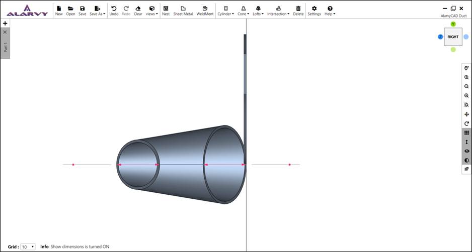
Fig 6.4.5 Right view
• On clicking Views then Left View.
• This displays the active page in Left view i.e., YZ Plane and -X direction.
• Refer Figure6.4.6.
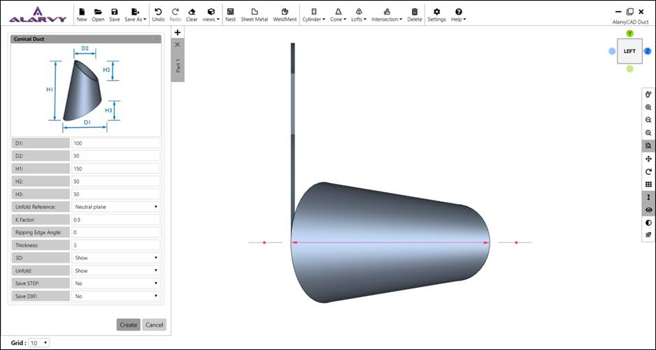
Fig 6.4.6 Left view
• On clicking Views then Back View.
• This displays the active page in Back view i.e., XZ Plane and +Y direction.
• Refer Figure6.4.7.
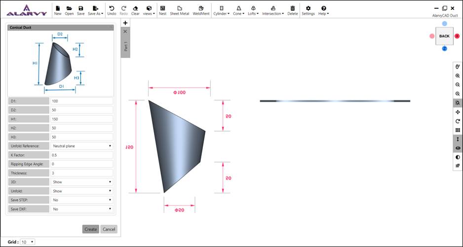
Fig 6.4.7 Back view
• On clicking Views then Bottom View.
• This displays the active page in Bottom view i.e., XY Plane and -Z direction.
• Refer Fig 6.4.8.
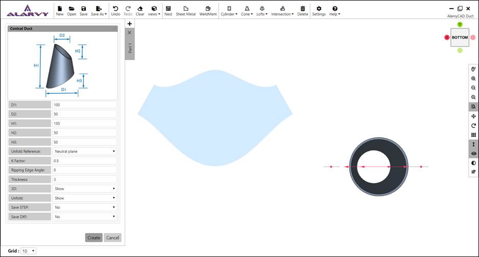
Fig 6.4.8 Bottom view
7.0 Settings and Help Toolbar
Fig 7.1 Settings and help toolbar
7.1 Settings
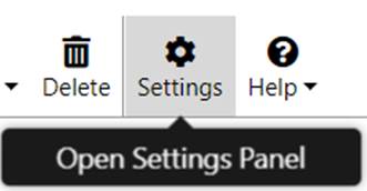
Fig 7.1.1 Settings button
• On clicking Settings icon, opens Settings Panel.
• Settings for Grid and Theme are available.
• Click on Save in settings panel to save the changes made by user.
• Click on Reset to reset the changes made by user to default values.
• Click on Cancel to discard the changes and close the settings panel.
7.1.1 Grid Settings
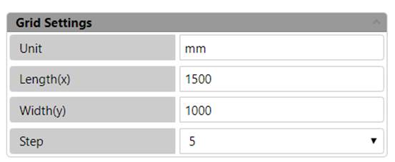
Fig 7.1.2 Grid settings
• On clicking Settings icon, Opens Settings Panel then Expand Grid Settings.
• Specifies below settings for Grid.
• Unit specifies Unit. By default, mm is selected.
• Length(x) specifies the grid length in X direction. Default value is set to 1500. This value is editable.
• Width(y) specifies the grid length in Y direction. Default value is set to 1000. This value is editable.
• Step specifies the distance between two line-segments in X direction or Y direction. Default value is 5. This value is editable.
7.1.2 Theme Settings
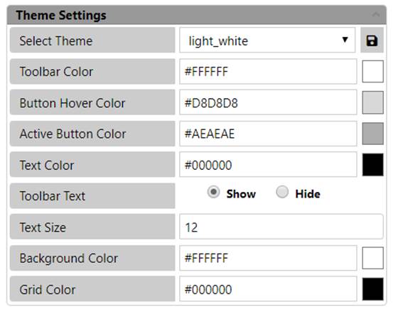
Fig 7.1.3 Theme settings
• On clicking Settings icon then Opens Settings Panel then Expand Theme Settings.
• Specifies Theme settings for the application.
Select Theme option
• Applies the selected theme to the application.
• Click on the dropdown to choose the available theme options.
• Changing the theme changes the colour of Toolbar, Button hover, active button, text, background and Grid.
• Standard theme attributes cannot be changed.
• To create a Custom theme first Choose Custom in dropdown then change the colour of all attributes, on clicking the Save button next to the dropdown then give a name to this custom theme then Click on.
Toolbar Colour option
• Specifies the colour of the Toolbar, Settings panel and Side toolbar.
• This is editable but on saving, it will be saved as a new Custom theme with a user specified name.
• On clicking the button next to the toolbar colour value, Opens Colour palette then Pick a colour for the toolbar.
• Toolbar colour of Standard Themes cannot be edited.
Button Hover Colour option
• Specifies the colour of the Buttons on Hovering in the toolbars, side toolbars, page tabs.
• This is editable but on saving, it will be saved as a new Custom theme with a user specified name.
• On clicking the button next to the colour value, Opens Colour palette then Pick a colour for the button hover.
• Button Hover colour of Standard Themes cannot be edited.
Active Button Colour option
• Specifies the colour of the active buttons in the page.
• This is editable but on saving, it will be saved as a new Custom theme with a user specified name.
• Click on the button next to the colour value option Opens Colour palette then Pick a colour for the active button.
• Active Button colour of Standard Themes cannot be edited.
Text Colour option
• Specifies the colour of the text in Toolbar, Settings Panel and Side toolbar.
• This is editable but on saving, it will be saved as a new Custom theme with a user specified name.
• On clicking the button next to the colour value, Opens Colour palette then Pick a colour for the Text.
• Text colour of Standard Themes cannot be edited.
Toolbar Text option
• Specifies whether text in Toolbar should be displayed or not.
• By Default, Toolbar text is set to ‘Show’.
Text Size option
• Specifies the size of the text in Toolbar, Settings Panel and Side toolbar.
• Default size is 12.
• Size is editable for all themes.
Background Colour option
• Specifies the background colour of the application.
• This is editable but on saving, it will be saved as a new Custom theme with a user specified name.
• On clicking the button next to the colour value, Opens Colour palette then Pick a colour for the Background.
• Background colour of Standard Themes cannot be edited.
Grid Colour option
• Specifies the colour of grid line segments.
• This is editable but on saving, it will be saved as a new Custom theme with a user specified name.
• On clicking the button next to the colour value, Opens Colour palette then Pick a colour for the Grid lines.
• Grid line colour of Standard Themes cannot be edited.
7.2 Help
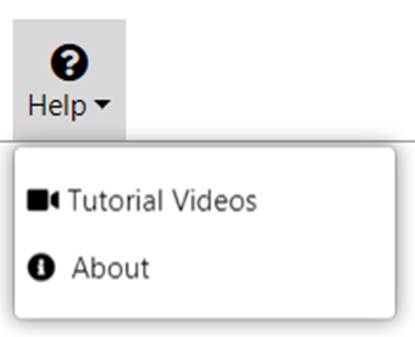
Fig 7.2.1 Help button
7.2.1 Help
• Opens help file for user understanding.
7.2.2 Tutorial Videos
• Opens a link to tutorial videos.
7.2.3 About
• Opens the user agreement, privacy policy, disclaimer, acknowledgement and other information of Alarvy duct application.
7.2.4 License Info
• Opens the information on the license type, start date and the end date.
8.0 Special features
AlarvyCAD application has below special features
• Rotator
• Contextual Help
8.1 Rotator
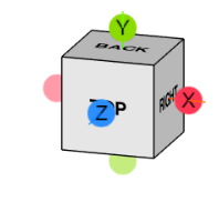
Fig 8.1.1 Rotator cube
• Rotator cube is positioned at top right corner of the page.
• It specifies the current orientation of the model and grid in the current page.
• Rotator has axis helpers – X, Y, Z starting from its centre.
• It also has view helpers (Spherical objects at the end of axis helpers). When clicked on the X, Y or Z balls, rotates the model in that direction.
• On clicking the axis balls, say X, rotates the view by 90 degree in X direction.
• There are 6 available default views with Rotator – Top, Front, Left, Right, Back, Bottom.
• Click on a view in cube face to see the respective Top or Bottom or Front view, etc of the 3D Model.
• Click on the Rotator cube and drag to see the corresponding rotated view of the model/grid.
• Rotating the model will rotate the rotator cube also to match the orientation.
• On multiple Page switch, Orientation of Rotator cube will be updated with the orientation of the model as in active page.
8.2 Contextual Help
• Contextual help is displayed at the bottom of the page.
• For example – When Dimensions ON/OFF button is clicked, it displays “Show dimensions is turned ON”.
• Refer highlighted part in Fig 8.1.2.
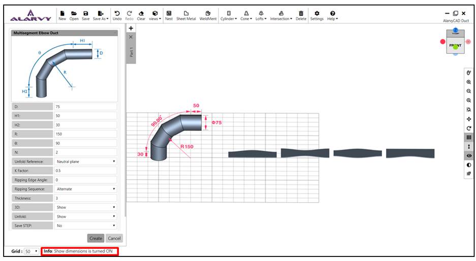
Fig 8.1.2 Contextual Help
• Contextual help displays the information on the parameter values
• Refer Fig 8.1.3 for example – showing the contextual help and dialog box ,Whereextension height of the Multisegment Elbow Duct (H1), should be greater than or equal to zero.
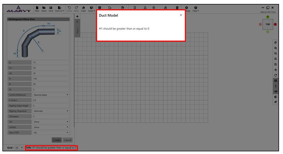
Fig 8.1.3 Contextual Help along with dialog box showing information on parameter values
9.0 Alarvy File Format
• Alarvy file format is in the form of json file.
• Click Save in File module toolbar to save the active page Turn part in *.alarvy file.
• Click Open in File module toolbar to open the *.alarvy file and render the Turn part in parameter UI.
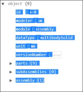
Fig 9.1 *.alarvy file top level
• Refer Fig 9.1 for *.alarvy file top level json structure.
• Contains the following fields –
o id – unique id of the duct model,
o modeler – name of the modeler, here it is ‘sm’,
o module name,
o datatype - ‘multibodySolid’ (as it can contain multiple duct models),
o unit - unit used in application,
o version number,
o parts – holds data of multiple models in the current page,
o subassemblies and
o assembly information
9.1 Parts
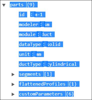
Fig 9.2 – Example of duct model in parts
• Holds the model data of all the duct model in the active page.
• Refer Fig 9.2 for duct model example.
• Each part model has below fields –
o Id – id of the part,
o Modeler – name of the modeler, here ‘sm’,
o Module – name of the module, ‘duct’,
o Datatype – solid model,
o Unit – unit used in application,
o Duct Type – Name of the duct, ‘cylindrical’
o Segments – Holds information on Sections of the duct, Operations and cutting planes
o Flattened Profiles – Holds information on points of the Unfold profile,
o Custom Parameters – Holds information on parameter values of the duct model and the other input parameters related to Unfold model,
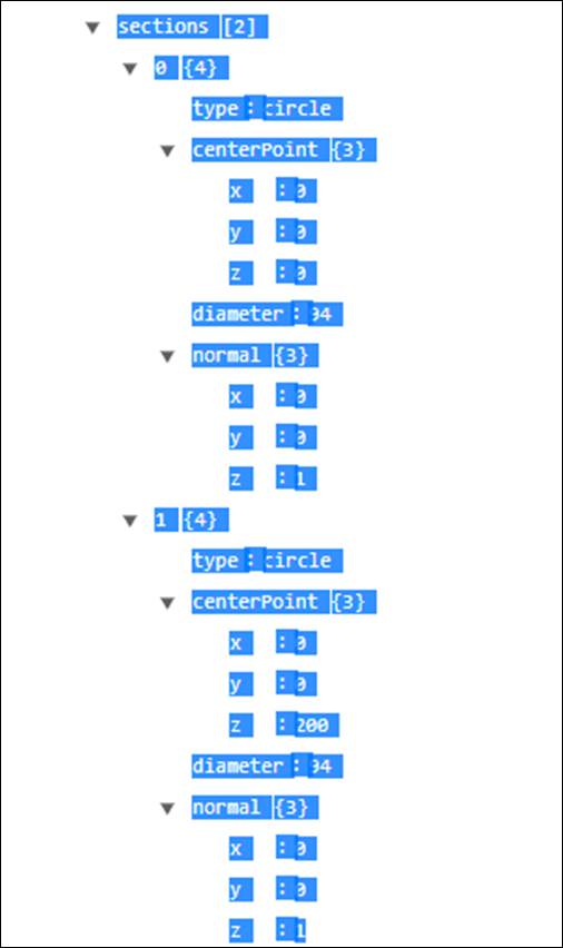
Fig 9.3 Sections of a cylindrical duct
9.1.1 Segments
• Segments contains three subsections, they are Sections, Operations and Cutting planes
• Section holds the data of the cross sectional data such as centre point, Internal diameter and the plane normal of the section as shown in the Fig 9.3
•Operations holds the data of the transform (rotation and translation) of the duct as shown in the Fig 9.4.
• Cutting plane plane holds the data of inclined faces of the cylinder (Such as the reference point of the top surface and bottom surface, where the plane is cut and there corresponding plane normal) as shown in the Fig 9.5.
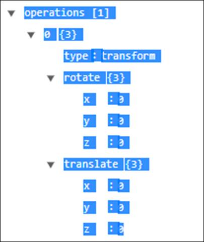
Fig 9.4 Operations of a cylinder
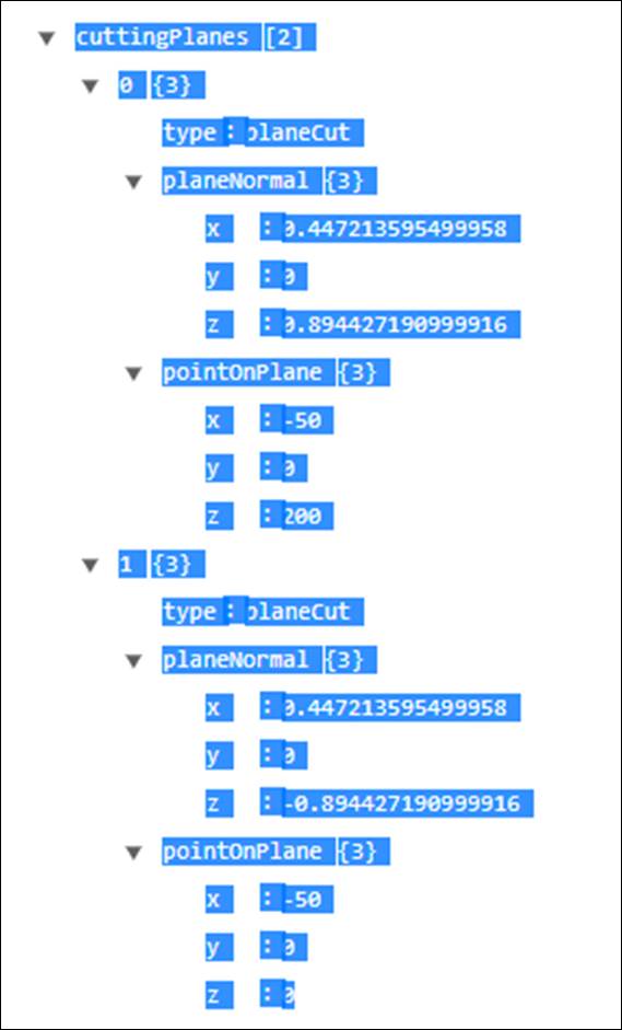
Fig 9.5 Cutting plane of a cylinder
9.1.2 Flattened Profiles
· Flattened profiles holds the data of the Unfold profiles as shown in the Fig 9.6.
· Points pertaining to the unfold profile (*.DXF format) are stored in an array as shown in Fig 9.1.
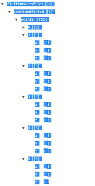
Fig 9.6 Unfold Profile data
9.1.3 Custom Parameters
· Custom parameters hold the duct parameter values as shown in the Fig 9.7.
· It also holds the input parameter data given by user through the parameter UI such as File format of 2D and 3D, display of 2D Unfold profile and 3D model, ripping edge angle, ripping sequence, data of 2D Unfold profile and 3D model, Unfold reference (Inner surface, Outer surface or Neutral plane) and K-factor.
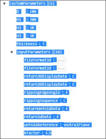
Fig 9.7 Custom Parameters