Alarvy 2D Nest Module
Alarvy 2DNest option is for nesting sheet metal parts, wood panels, fabric cuttings, paper cartons, leather, stickers, etc. It provides compact layouts and reduces scrap to a great extent thereby reducing material cost.
Stock Data
The Stock Data panel allows you to define and manage the sheets (materials) upon which your parts will be nested.
Adding Standard Sheets (+ Button)
Click the + button in the Stock Data header to instantly add a new stock item with standard default dimensions.
|
|

Predefined Sizes & Manual Dimensions
• Drop-down Selection: You can choose a standard sheet size from the drop-down menu (e.g., 2500X1250, 3000X1500, 2400X1200 mm).
|
|

• Direct Editing: You can customize the dimensions at any time by editing the X-Length (width) and Y-Length (height) input fields. The stock type label will dynamically auto-adjust to reflect your new custom size.
|
|

Loading Custom DXF Stock
Click the Load Stock button to import DXF files. The system will parse the drawing geometry, enabling you to perform nesting inside custom-shaped sheets or leftover remnants.
|
|

Sheet Quantity (Count)
Modify the Quantity field to specify how many sheets of each stock size are available for nesting. The algorithm will only use sheets up to the specified limit.
|
|

Nesting Parameters
The Parameters control panel configures the layout engine, clearance boundaries, and optimizations.
|
|

Margins (mm)
• Top, Bottom, Left, Right: Define sheet-edge boundary offsets where no parts can be nested (crucial for clamp clearance and sheet-handling systems).
• DXF Stock Margin: A uniform offset applied specifically when a custom-shaped stock is loaded from a DXF file to ensure parts are safely offset from non-standard edges.
Incremental Angle
• Incremental Angle: Specifies allowed part orientations. For example, if the incremental angle is 90 then allowed part orientation will be [0, 90, 180, 270] degrees.
• Free Rotation: If free rotation is enabled, there is no restriction on the allowed part orientations.
Part Distance
• Part Distance: Specifies the minimum clearance/gap required between nested parts.
• Common Line: Checking this option sets the Part Distance to 0 mm and enables common-line cutting. In common-line nesting, the common edges are removed and edges are merged, which reduces cutting path travel.
DXF generated for common line nesting with common edge removal and edge merging
Mirroring
Toggles whether the nesting engine is allowed to mirror (flip) parts.

Nesting Direction
Governs the packing progression of parts on the sheet.
• YX (Vertical-First): Packs parts along the Y-axis first, transitioning to the next column along the X-axis once full.
• XY (Horizontal-First): Packs parts along the X-axis first, transitioning to the next row along the Y-axis once full.
Part Data
The Parts Data panel lets you manage the list of shapes you intend to cut.
Loading DXF Files
Click Load Parts to import single or multiple .dxf files. Users can either upload individual part files in DXF format or upload a single DXF file containing all the parts and load them in a single go. Users can easily change the quantity of each part as required.
|
|

Adding Rectangular Parts
Click the + button in the Parts Data header to instantly add a rectangular part of size 100X100. The length and width of a rectangular part and the quantity can be easily edited as required.
|
|

Saving & Exporting
Once nesting is complete, you can save or export your results using the buttons in the Report panel.
|
|

Save:
Click Save to generate an “.alarvy2dnest” file. This saves your complete project state (stock, parts, parameters, and results) so you can easily reload it later using "Load Nesting File" without losing your work.
|
|

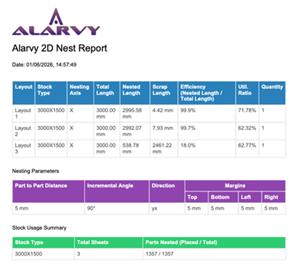
Download PDF:
Click Download PDF to export a detailed, printable report. It automatically includes:
• Data Summaries: Tables outlining stock usage, cutting efficiency, margins, and scrap lengths.
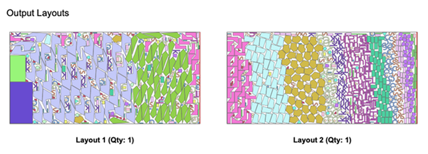
• Visual Layouts: Visual diagrams of every nested sheet showing exact part placement.
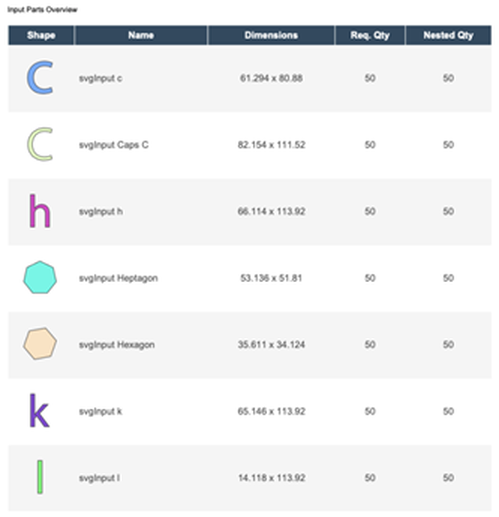
• Parts Overview: A visual list of every part you uploaded for nesting. It displays a small thumbnail image of each shape alongside its dimensions, the total quantity you requested, and the actual quantity that was successfully placed onto the sheets.
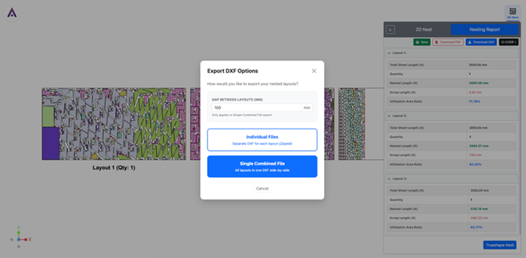
Download DXF:
Click Download DXF to export the cutting profiles for CNC/Laser machines. You can choose:
• Individual Files: Creates a ZIP file containing a separate DXF for each nested sheet.
• Single Combined File: Places all nested sheets side-by-side in one single DXF file (you can define the gap between sheets).
G-Code Generation and Toolpath Simulation
You can click on the G-Code button present in the nesting report panel and it will provide option to generate G-Code or run the tool-path simulation from a G-Code file.
|
|

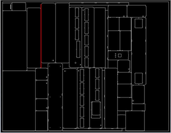
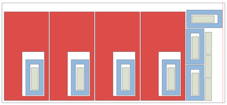
The G-Code will be generated such that the laser cuts the inner most parts first and then cuts the outer loops and parts. For instance, in the nested layout shown below, the light green coloured part is nested inside the hole of the blue coloured part, which is again nested inside the hole of the red coloured part. In this scenario, the G-Code will be generated such that the laser cuts the light green coloured part first followed by the blue coloured part and then finally the red coloured part.
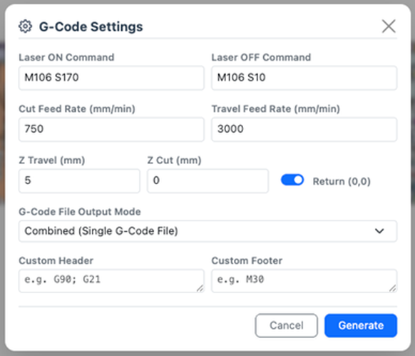
G-Code Generation
Clicking on the generate G-Code option will display the G-Code settings panel where user can edit laser on/off command, cut feed rate, travel feed rate, Z travel, Z cut and also provide custom headers and footers if required.
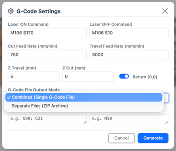
If you have multiple nested layouts, you can either save each layout as individual G-Code file or save a single combined G-Code file as required.
Toolpath Simulation
Clicking on the Toolpath Simulation option will open the tool-path simulation window where the generated G-code file can be uploaded.
|
|

Hide/Show Rapid Movement
This option is used to show or hide the toolpath movement when the laser is turned off. If rapid movement is enabled, then the laser movements are highlighted in red colour while the laser cuts are highlighted in green.
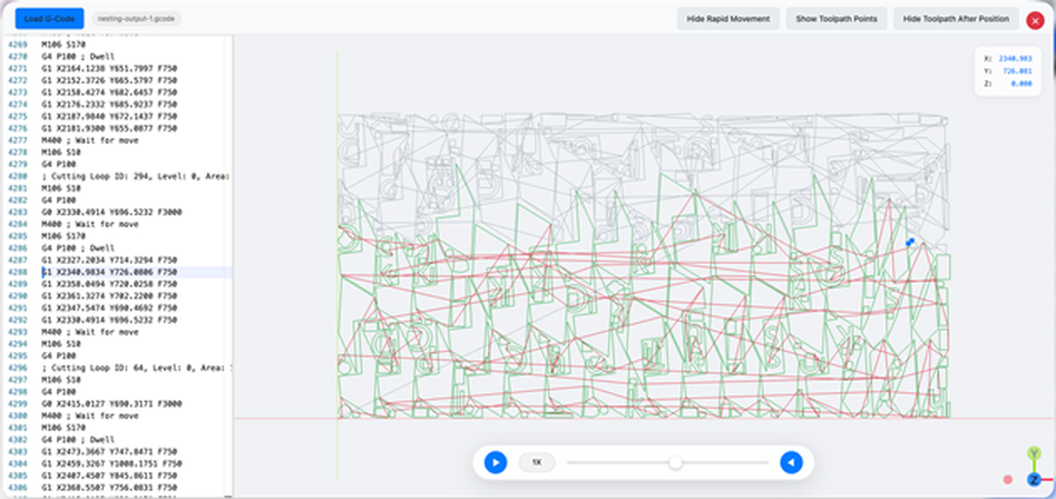
Toolpath simulation with rapid movement enabled
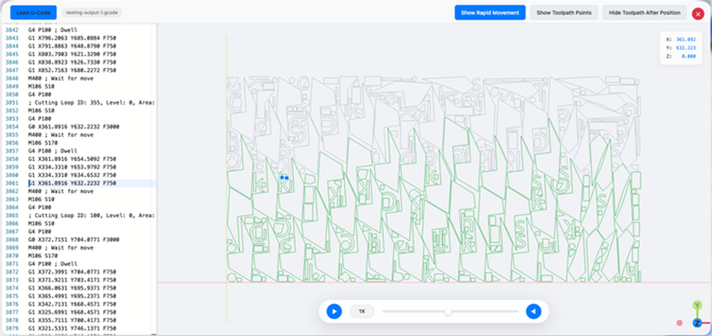
Toolpath simulation with rapid movement disabled
Show/Hide Toolpath Points
This option can be used to show or hide the toolpath points.
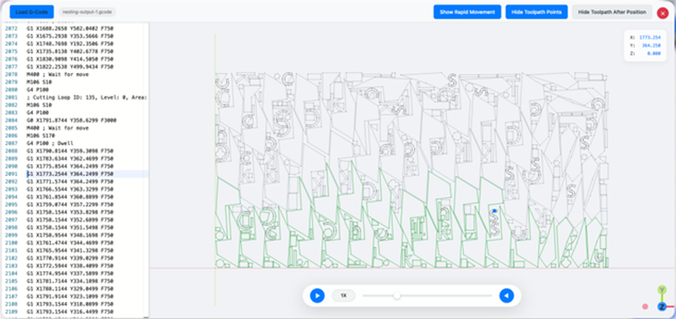
Toolpath simulation with toolpath points enabled
Show Toolpath After Position
This option is to show or hide the preview of the nested layout while running the simulation.
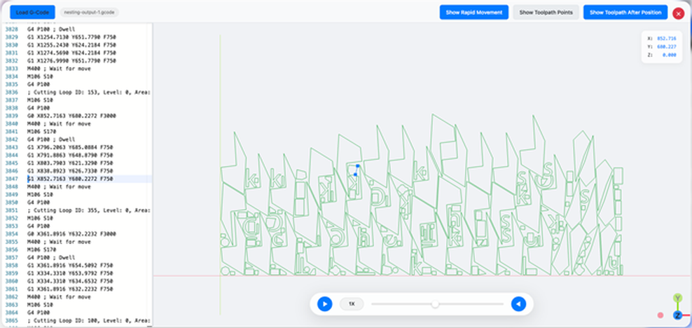
Toolpath simulation with show toolpath after position disabled

Toolpath simulation with show toolpath after position enabled